

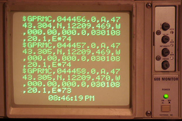
Startup screen Displaying NMEA output
If you ever experiment with microcontrollers, you know you need a way to get status information from your microcontroller and you don't want to use a lot of precious pins to do that.
Serial devices are by far the easiest way to do this since most microcontrollers (at least AVRs) have a serial device built-in. Simple code is minimal and you only need to sacrifice 1 pin to be able to send output.
The problem with a plain serial port is that you need a terminal device, usually a computer, but the computer isn't always conveniently located near the work bench. LCD displays are very nice but require quite a few pins and added code. Some people buy or build a serializer board for their LCD display, including its own microcontroller to provide an effective display device.
A device that frequently is located on your workbench, but mostly doing nothing, is an oscilloscope. What if you could use that oscilloscope as a display device for your microcontroller projects?
Enter the Dutchtronix AVR Oscilloscope Terminal:
|
13 or 14 lines, 20 characters per line | |
|
Displays full ASCII character set including upper and lower case | |
|
Automatic superfast scrolling | |
|
Flashing cursor | |
|
Delayed CR/LF control | |
|
Current time is displayed and updated at the bottom of the screen (customizable) | |
|
Multiple Baud Rate support. | |
|
Persistent Vector graphics support (max 128 vectors). As of firmware V4.0. | |
|
Incorporated in the Dutchtronix AVR Oscilloscope Clock firmware V3.5 and up. |
This terminal is an application built in the Dutchtronix AVR Oscilloscope Clock H3-1, firmware 3.5 or above. You can use a standard serial cable to connect the AVR Clock to a computer running a terminal program. This way, you can try out the AVR Terminal for example by using your terminal program to send a large text file to the AVR terminal. You'll notice the incredible scrolling speed, without losing data (up to about 38,400 bps.)
Connecting the AVR Terminal to a device that sends out text over its serial port is much more useful, but it can also be frustrating to get going because of 2 issues:
|
Serial Communication can electrically be done in at least 2 ways:
| |||||
|
The serial connectors on the AVR Clock expect RS-232 levels. However direct access to the AVR Serial Port, which operates at TTL levels, is available on the center pin of the RXROUTE header. Select the electrical connection appropriate for the device sending the information over the serial line |
|
Serial communications is based on a TX line and an RX line. You need to make sure that the TX line of the sending device is connected to the RX line on the AVR Clock (pin 3 of the DB9 or RS232 header connector). The serial cable used to communicate with a standard PC will probably not work! Making a custom serial cable is by far the easiest solution; that way you can switch cables to talk to a PC or to a microcontroller circuit. An alternative is to connect a "NULL MODEM" connector to your existing cable to switch the RX and TX lines. Make sure you pay attention to the DB-9 connectors used on your cabling: there are male ones and female ones. |
Once you have conquered these issues, you're in business. Good luck and enjoy!
Operating Instructions:
Select the on-screen menu in the AVR Oscilloscope Clock (S1 short push), advance to the "App" field using S2 short pushes, then cycle to the "Term" application using short pushes on S1 and select this option (S2 short push).
The AVR Terminal starts up at the current baud rate of the AVR Clock (19,200 baud by default). You can change the baud rate in the on-screen menu (S1 short push). The AVR Terminal will display every incoming character within the full 7-bit ASCII range. The following non-displayable characters are interpreted: BS (08), HT (09), LF (10), CR (13). Other non-displayable characters like ETX (decimal 3) are displayed using the ^ character, in this case "^C". Look here for an overview of the ASCII character set.
The AVR Terminal will display a blinking cursor at the current position about 1 second after receiving the last incoming character. This delay prevents a lot of useless setup when a burst of character is being received.
The AVR Terminal uses a delayed Linefeed mechanism to process control characters. The reason for this is that you don't want to advance to the next empty line (and possibly scroll the display) until an actual character is ready for that next line. A Linefeed (LF) character advanced to a new line but only when a character for that new line is received. Normally, the blinking cursor indicates the location where the next incoming character will be displayed. However, if a LF is pending, the cursor will be on the last character of the current line (or when the line is full since this implies a LF).
The CR character followed by a printable char is interpreted as a Carriage Return, meaning the cursor goes back to the beginning of the line (without blanking the line), so that you can potentially update the same line with status information by repeatedly sending a status line, followed by a CR. A CR character followed by an LF character is treated as just an LF character. Where two or more CR characters in a row are received, all but the first one are interpreted as LF characters. To advance to the next line, please use an LF character, or 2 CR characters.
When using a terminal program like HyperTerminal or Bray's Terminal to send lines of text to the AVR Terminal, please select the option to include a LF with the CR character; both programs provide this option.
To change the time, select the clock application from the on-screen menu and use the regular procedure to change the time.
The burn-in protection feature of the Dutchtronix AVR Oscilloscope clock moves the screen around 1 pixel in various directions at intervals that can be set by the user using the "Burnin" field in the menu. However, this automatic moving around may interfere with user graphics on the screen; for example borders drawn at the edge may suddenly disappear if the screen is moved 1 pixel. Therefore, burn-in protection is disabled by default, while in terminal mode. It can be enabled using the IOCTL configuration word (a command line only option)
The bottom line of the terminal image shows, by default, the Numeric Display from the Clock. This conveniently shows the time or date. It is possible to suppress this Numeric Display and increase the number of terminal lines from 13 to 14 using the IOCTL configuration word.
Vector Graphics
The terminal application in firmware V4.0 now does more than just text display; it also support vector drawing; vectors are simply lines on the terminal screen drawn from pixel position X0,Y0 to X1, Y1. The vectors are persistent, meaning that you only have to send a "draw vector" command to the terminal once, and the vector stays on the screen until you tell the terminal to change it or stop drawing it. The current implementation supports up to 128 individual vectors to be drawn simultaneously, together with characters. Keep in mind that the refresh rate of the terminal is reduced as more and more information is being displayed on the screen. The characters and vectors on the screen are separate graphics planes.
A sample demo application called Asteroids is included (in source form) with the Dutchtronix AVR Oscilloscope Clock firmware. This demo can run either on a Windows PC, or on another AVR. This demo sends the proper codes to the terminal program to display moving asteroids, a mother ship and bullets using the new vector graphics. Communication is done through the serial port (or USB to Serial Converter, if your Dutchtronix AVR Oscilloscope Clock board is equipped with the FT232RL IC).
Pixel positions X and Y can have any value between 0 and 255. Pixel position X = 0 is the LEFT most pixel on the screen; pixel position Y = 0 is the TOP most pixel in the screen.
Character positions, used to set the cursor to a specific location, refer to location of a character (not pixel). The range of the X value (position in a line) is 0..19. The range of the Y value (line position) is 0..13 (though the default range is 0..12)
Q: How do I control vectors in the terminal program?
A: The Dutchtronix AVR Oscilloscope clock maintains a table with room for 128 vectors. These vectors are set by the user using the "Vector Entry" graphics command. By defaults, none are displayed. The user can tell the terminal program to start displaying all or part of this table using the "Vector Range" graphics command.
Q: How do I send Enhanced Graphics Data to the terminal program?
A: There are currently 7 Graphics Commands implemented. Each one is activated by sending the "Graphics Escape" value 255 (0xff in hex) to the terminal program. The 6 commands are:
|
Vector Entry. Takes 5 argument bytes: 1 vector
index + 4 vector pixel position bytes(x0, y0, x1, y1) | |
|
Vector Range. Takes 2 argument bytes: starting
index and length. Length may be 0 meaning no vectors are being displayed. | |
|
SetCursorPosition. Takes 2 argument bytes, char
position X and char position Y | |
|
SetCursorControl. Takes 1 argument byte: ON (1)
or OFF (0). Control the flashing cursor. Usually OFF when doing vector
graphics. | |
|
SetClockLine. Takes 1 argument byte: ON(1) or
OFF(0). By default, the bottom line of the terminal screen displays the
numeric clock value. Turning this Clock Line off increments the number of
lines on the screen from 13 to 14. | |
|
SetBurnIn. Takes 1 argument byte: ON(1) or
OFF(0). Burn-In protection moves the screen around 1 pixel at a time at user
defined intervals. This feature is turned off by default when running the
Terminal Application, but the user can override this default using the IOCTL
configuration word. The SetBurnIn graphics command allows the application to
make sure the Burn-In prevention is turned ON or OFF. | |
|
SetTermCtrl. Takes 1 argument byte: 0 means
Clear Screen. Other controls will be added as needed. |
Other bytes sent to the terminal program are displayed as regular chars, if they are in the ascii range 0..127, where values 0..31 are handled as control characters.
Graphics commands are all multi-byte and each command needs to be completed within 1 second, or the terminal program will reset itself to accept characters. This prevents invalid input data from confusing the terminal program too much.
The Asteroids demonstration program
The Asteroids game was written by Christopher Ladden @ liquidware.com, inspired by the old Atari Vector Graphics game.
The Asteroids game uses Vector Graphics so you'll need the Dutchtronix AVR Oscilloscope firmware V4.0 or higher to run the game.
There are 2 versions, one running on a Windows PC (Windows XP and up, needs (virtual) serial port) and one running on an AVR running at 16 Mhz; the AVR needs some push button switches connected to PB0..PB3 (1 minimum). Output on optionals LEDs is available (PD0..PD1), as well as sound (on OC1A-OC1B).
The download contains the source code for these games. Directory "Asteroids" builds the game for an Atmega2560, which is the AVR included with the STK-600 development board; I used Winavr-20100110 to build the AVR program. Directory "VectorGen" builds a Windows console application, using the shared source file "Asteroids\asteroids.c". I used Visual Studio 2008 to build the program but expect earlier Visual C++ version to work just fine.
Q: How do I play the Asteroids game?
A: Try to shoot bullets from the mothership to the flying asteroids. Controls differ for the 2 supported hosts:
Windows PC:
Space to shoot
Right Arrow to turn the ship clockwise
Left Arrow to turn the ship counter clockwise
Up Arrow to move the ship forward
x or X to exit the game
baud rate is set for 115,200 bps
Program is called "vectorgen.exe" in the archive
Default is com1: but this can be changed on the command line
STK-600:
SW0 to shoot
SW1 to turn the ship clockwise
SW2 to turn the ship counter clockwise
SW3 Arrow to move the ship forward
LED0 is a seconds indicator
baud rate is set for 250,000 bps
Sound generation supported
LED1 blinks when the generated serial out data cannot be transmitted fast enough (serial out ring buffer full). The application will wait in that case (automatically).
program is "Asteroids.hex" in the archive, compiled for the Atmega2560 AVR.
STK-600 instructions using STK600-ATMEGA2560 board (included with STK600):
|
set clock to 16 Mhz. | |
|
connect ports PB0-PB3 to SW0-SW3. | |
|
connect ports PD0-PD1 to LED0-LED1 | |
|
connect ports PE0-PE1 to RXD-TXD on RS232 Spare | |
|
Sound available on pins PB5-PB6 (OC1A-OC1B) | |
|
Use a Female to Female RS-232 cable with a "NULL MODEM" adapter |
Dutchtronix AVR Oscilloscope Clock instructions:
Connect the serial link to the device running the asteroids game (PC or AVR)
set the baud rate to 115,200 (for Windows PC) or 250,000 (for STK-600)
Select the Terminal Application
Download Asteroids Demo Source Code
It is also possible to use a separate USB to Serial Converter device. I recently (February 2017) purchased a "FT232RL 3.3V 5.5V FTDI Serials Adapter Module Mini USB Port f. Arduino to TTL D" unit on Ebay ($2.08 incl. shipping). This unit uses the FTDI chip which has good driver support. It works but, like all these separate USB to Serial converters, is much slower than the built-in serial port or the on-board FT232RL. As a result, the sample Vector Graphics demo application Asteroids won't work very well. You may want to experiment with the port settings on your PC ("USB Transfer Sizes" and "Latency Timer") to get the best possible results.
About Display Quality
Using a microcontroller to drive an Oscilloscope as a display device is somewhat of a compromise. The oscilloscope beam needs to move all the time to provide an even picture. When the AVR gets very busy, for example when it is receiving a massive amount of text, you will notice a bright spot at the lower right corner of the time display. Even though the Serial Port is completely interrupt drive, the AVR needs to process the buffered characters in between screen refreshes and cannot move the beam while doing that. When the screen is empty, the clock display line becomes quite bright, because the AVR does nothing but display the clock line. In other words, the refresh rate is going up. The intensity control provided on the Dutchtronix AVR Oscilloscope Clock board (marked 'Z') is quite effective at suppressing the bright dot.
When playing the Asteroids demo, you may notice a certain "restlessness" in the displayed chars and the game boundary lines (the asteroids move too fast to notice); almost like "dot creep". This is caused by the large number of serial input interrupts, necessary to receive the display control data from the computer running the game: up to 12,500 per second.
Dutchtronix AVR Oscilloscope Clock Hardware 2.0
If you have upgraded your Hardware 2.0 clock by replacing the Atmega168 with an Atmega328p AVR, you are able to run a special version of the V4 firmware (contact me). Due to the parasitic level shifter used on that board, the maximum baud rate is 57,600. Please modify the Asteroids Demo Source Code to run the game at that baudrate. The baudrate on the AVR Clock itself can be set using the menu <short S1>
Back to Dutchtronix AVR Oscilloscope Clock
![]()
![]()
![]()
![]()