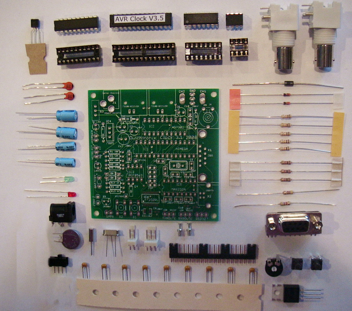
Assembly Instructions of the Dutchtronix AVR Oscilloscope Clock, Hardware 3.1
Please use the pictures and parts list below as a reference. Most of the components can be easily identified and they are clearly marked on the PCB. A complete parts list is available here (courtesy of B.B.).
Here is some extra information:
Correction:
Resistors R7 and R8 are marked as 2K on the PCB labelled 2008 but their actual value is 1K
|
Pay attention to:
|
The following components are unpopulated in the Clock kit:
|
Cable Connection:
|
The easiest method to power the AVR Oscilloscope clock is to use an external wall wart, voltage range 7-15V, with a 5.5 mm (external diameter) center positive DC connector. | |||||||||||||
|
The AVR Oscilloscope Clock kit can also be powered by an external 5V regulated power source. | |||||||||||||
|
The on-board RS-232 level Serial Port can be used for:
The onboard female DB-9 connector allows the use of a standard Serial Cable. Such a cable has one female DB-9 connector and one male DB-9 connector. The male DB-9 connector plugs into the female DB-9 connector on the clock. These cables also connect the proper RX and TX pins on each side of the cable (crossover cable.) However, a 3-pin polarized header is also available for use with a custom cable, similar to the original Dutchtronix AVR Oscilloscope Clock Hardware 2-0.
Pin 1 on the RS232 3-pin polarized header is the right-most pin. It is marked on the PCB but invisible once you install the header. Your connector must match this. |
Other instructions:
|
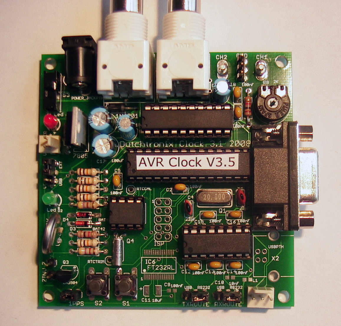
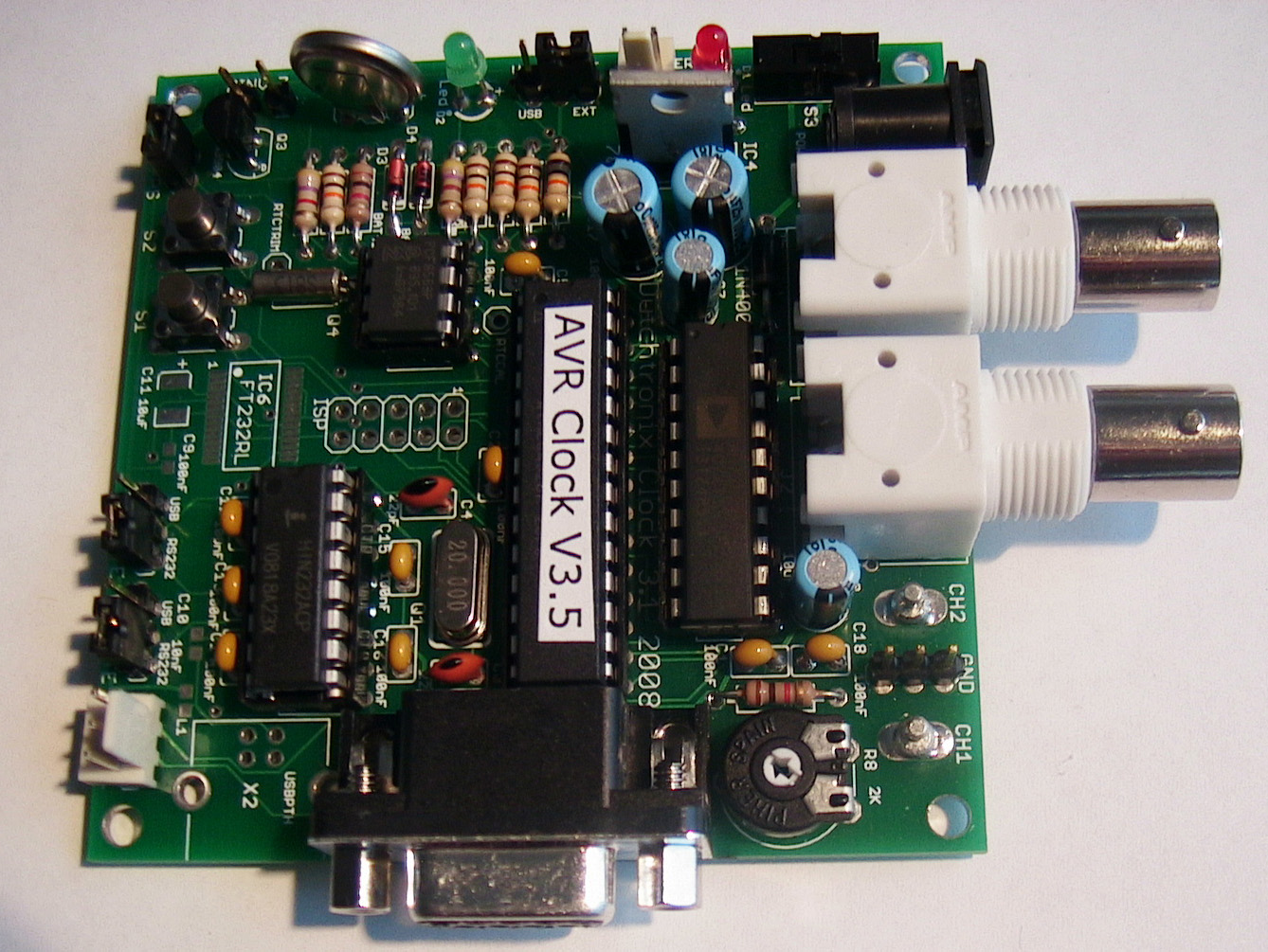
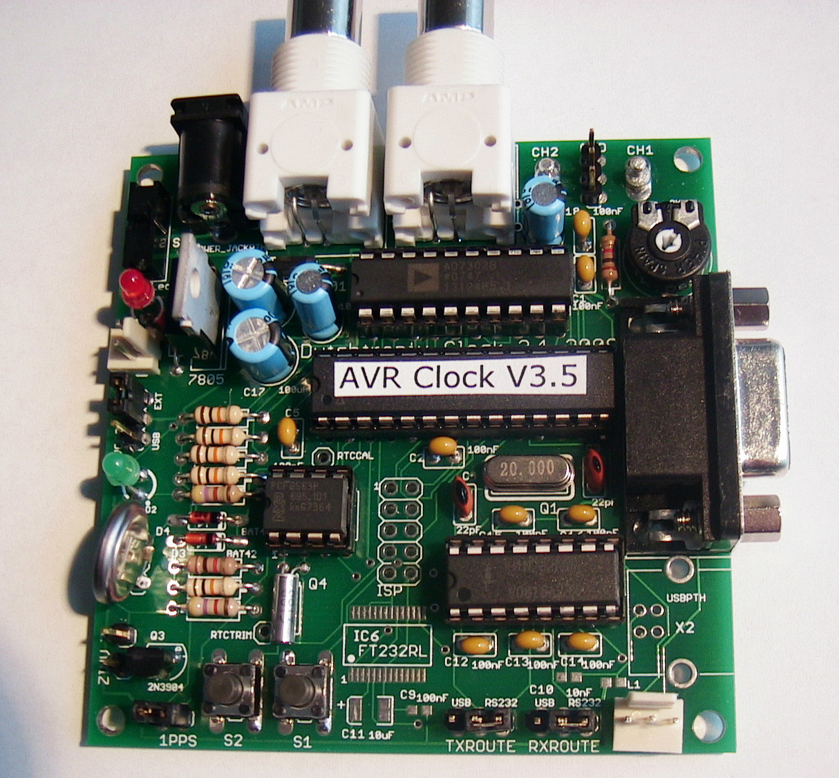
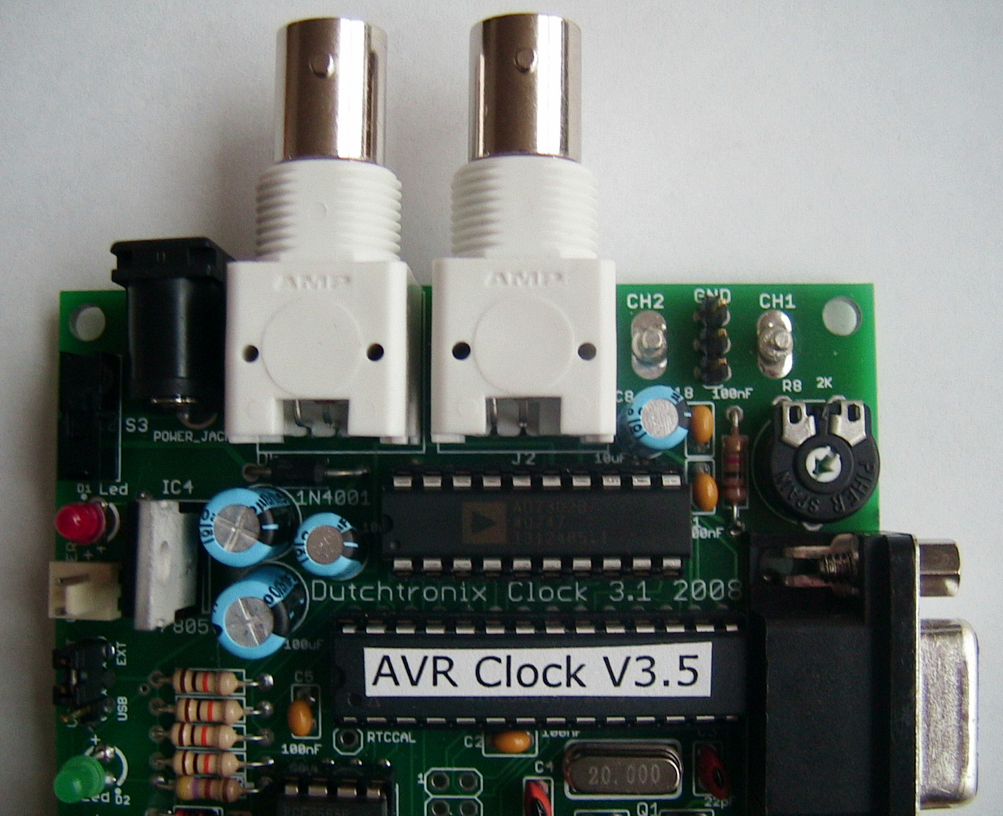
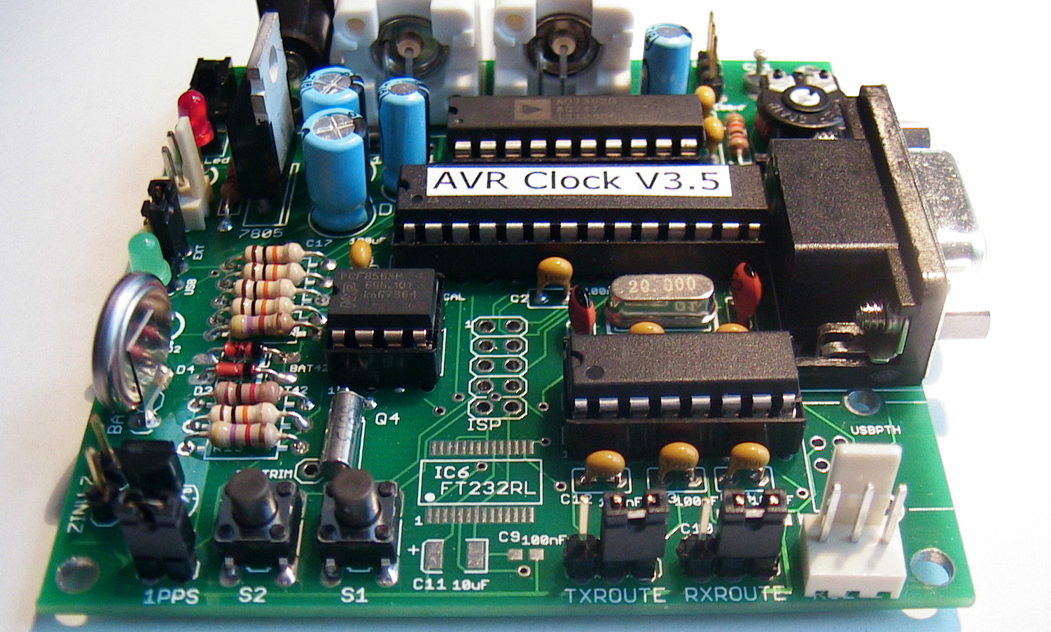
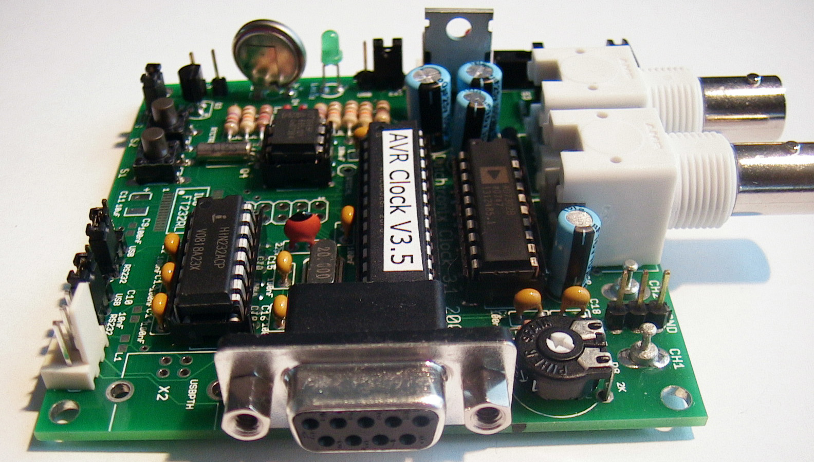
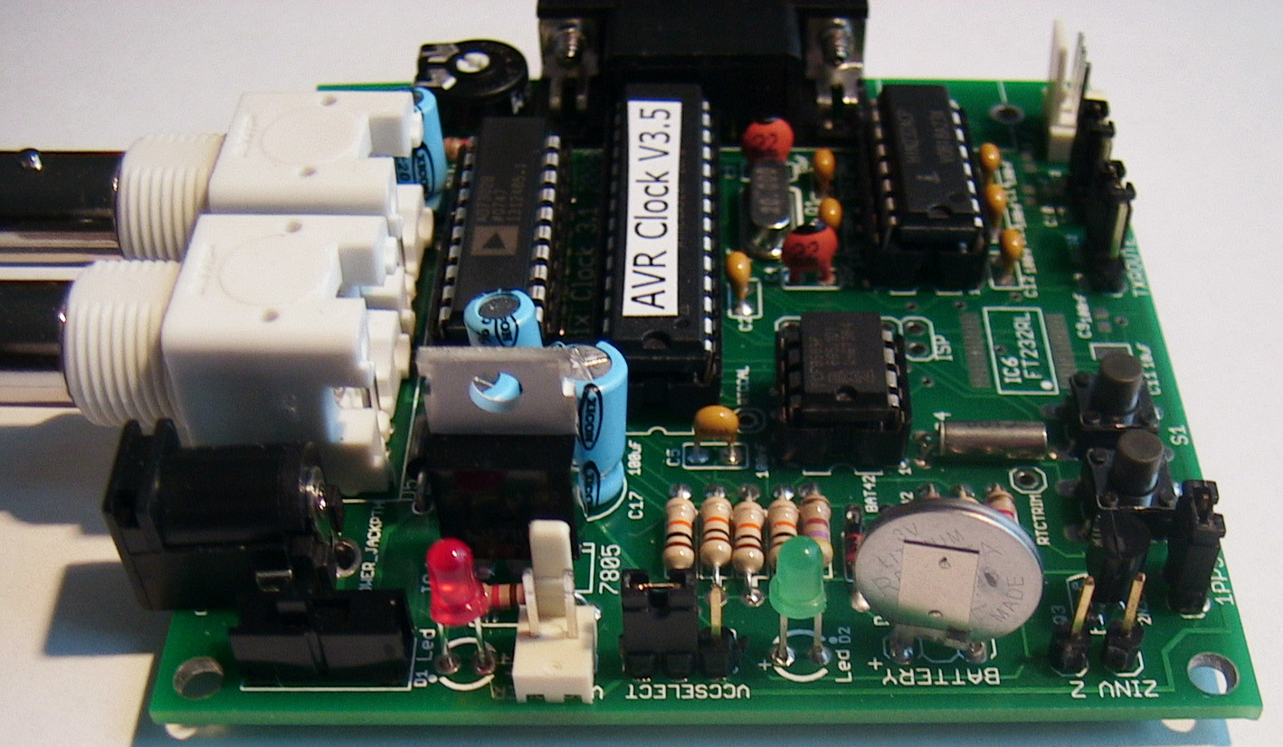
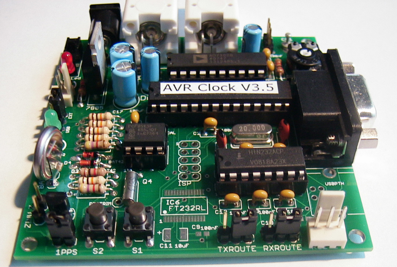
Pictures of the assembled board:
|
|
|
|
|
|
|
|
|
 |
 |
 |
 |
Parts List Dutchtronix AVR Oscilloscope Clock
hardware 3.1 kit
|
Printed Circuit Board H3.1 |
1 |
PCB |
|
|
ATmega328p-20PU Microcontroller |
IC1 |
1 |
Preprogrammed CPU |
|
AD7302 D/A Converter |
IC2 |
1 |
Creates Voltage levels |
|
NXP/Philips RTC PCF8563 |
IC3 |
1 |
RTC. Only available on Ebay |
| HIN232ACP Level Converter | IC5 | 1 | RS-232 |
|
Lithium battery |
BATTERY |
1 |
Keep time when turned off |
|
20 Mhz crystal HC-49/US |
Q1 |
1 |
CPU Crystal |
|
32Khz crystal |
Q4 |
1 |
for RTC |
|
BAT-42/BAT-85 schottky diodes |
D3-D4 |
2 |
Battery Protection |
|
1N4001 diode |
D5 |
1 |
Reverse polarity protection |
|
1K Trimpot |
R8 |
1 |
Reference Voltage |
|
Momentary Tactile switch |
S1-S2 |
2 |
User Interface |
|
Power Switch |
S3 |
1 |
Power |
|
3 mm red led |
D1 |
1 |
Power indicator |
|
3 mm green led |
D2 |
1 |
User Interface |
|
LM7805 |
IC4 |
1 |
Power Supply regulator |
|
2N3904 NPN |
Q3 |
1 |
Intensity Inverter |
|
2-pin header |
POWER-M |
1 |
Power |
|
3-pin RS-232 connector socket |
RS-232-F |
1 |
RS232 |
|
10 uF cap |
C7-C8 |
2 |
Power stability |
|
100 uF cap |
C6,C17 |
2 |
Power stability |
|
22 pF caps |
C3-C4 |
2 |
For Atmega Crystal |
|
100 nF cap |
C1-C2,C5, |
9 |
Power stability, DC-DC |
|
10K pull-up resistors |
R1-R5 |
5 |
Glue |
|
1K resistor |
R6-R7,R14 |
3 |
Glue |
|
470R Resistor |
R9 |
1 |
LED current limiter |
|
4K7 Resistor |
R13 |
1 |
Intensity Inverter |
| 28 pin socket | IC1 socket | 1 | CPU |
| 20 pin socket | IC2 socket | 1 | DAC |
| 8 pin socket | IC3 socket | 1 | RTC |
| 16 pin socket | IC4 socket | 1 | RS232 |
|
2-pin header |
JP6 |
1 |
1 PPS feed |
|
3-pin header |
GND |
1 |
Ground for probes |
|
1-pin header |
Z |
1 |
Intensity Control |
|
1-pin header |
ZINV |
1 |
Intensity Control |
|
3-pin header |
VCCSELECT |
1 |
Power source Selection |
|
3-pin header |
RXROUTE |
1 |
RS232 |
|
3-pin header |
TXROUTE |
1 |
RS232 |
|
shunt for headers |
SHORT |
4 |
Various |
|
Turret Terminals |
CH1-CH2 |
2 |
Scope connectors |
|
Power Jack |
J1 |
1 |
Power |
| DB-9 connector | X1 | 1 | RS232 |
|
BNC connectors |
J2-J3 |
2 |
Scope Connectors |
Back to Dutchtronix AVR Oscilloscope Clock
![]()
![]()
![]()
![]()