Dutchtronix AVR
Oscilloscope Clock Hardware 3.1 FAQ
Firmware Version 4.3
March 31, 2021
Sections:
The following description applies to the Dutchtronix AVR Oscilloscope Clock, hardware 3.1. This board allows the user to display various clocks on an analog CRT device, like an oscilloscope, and control the options using the on-board push buttons S1 and S2 using on screen menus, all powered by an external wall wart (user provided). The board also includes a true RS-232 level Serial Interface. The Dutchtronix hardware 3.1 PCB has a footprint for a USB interface.
Dutchtronix is proud to present the firmware version 4.2 for the Dutchtronix AVR Oscilloscope Clock.
Features in firmware V4
General Features (already available in firmware V3)
|
Q: What kind of oscilloscope can I use?
A: Any analog scope with X-Y mode should work without problems. Low-end digital scopes will surely not work, High-end digital scopes may work (Tektronix TDS3034B and HP54600B work well, Tektronix 2014B works ok) . High-end analog scopes (400 MHz or better) like the Tektronix 7904 or 7854 will have some flicker because their phosphor decay time is so short; this will make the picture look less stable, even at a refresh rate of over 150 times a second. On scopes like the Tektronix 465 and 475, the picture is rock solid.
Q: What kind of cables should I use to connect the clock to the oscilloscope?
A: The easiest way to connect the AVR clock to your scope is to use two BNC cables. It is also possible to use probes with pincer tips. The CH1 and CH2 turret terminals were selected to be easily useable for probes with pincer tips. The BNC connectors are congruent to the turret terminals: CH1 is on the right side, CH2 on the left side (when holding the AVR clock so that the silk screen text can be read. The AD7302 DAC is a low output impedance DAC which allows the use of 1X probes, BNC cables or straight wires; 10x probes will also work. Connect the scope’s intensity control to the Z or ZINV output of the AVR clock to improve the image even more.
Set the scope in X-Y mode and connect the cables or probes to channels 1 and 2. Turn R8 all the way counterclockwise (maximum image size). Set both channels to DC mode and the voltage range to 0.5V per division. Now turn R8 clockwise to make the image fit your screen. You can tweak the image, for example to make it completely square (8 divisions), by manually reducing the voltage per division value (VAR knob.) If your scope does not support 0.5V per division, reduce the image size by turning R8 until the generated images matches your scope.
Most scopes define CH1 and the X axis and CH2 as the Y axis. Some, for example the Tektronix 485, reverse this convention. As a result, you will need to swap the probes.
Please note that if the image looks distorted when using 10x probes, you may have to adjust the probe compensation (they usually have a small adjustment screw).
Q: How do I power the AVR clock?
A: Use a standard wall wart which generates somewhere between 8 and 15V DC and has a 5.5mm outside diameter DC power plug, center positive. This is the most common DC power plug used. The kit includes such a plug. The AVR Clock has protection against reverse polarity. You can also connect a 5V regulated power source directly to the 2 prong adapter, + side is marked. The +(positive) is on the side of the power regulator circuit, the –(negative) is next to the VCCSELECT header. When using an external wall wart, +5V is present on the VCCPOWER connector; you can use this to provide power to other projects since the 7805 regulator is oversized. One possible application is to power a GPS unit.
Q: How are the on-board
button switches operated?
A: There are 2 push button switches, S1 and S2. Each switch has 2 actions: long push (> 1 second,
hold until you see a change) and
short push (<1 second, push and release). Switch S1 also has
auto-repeat capabilities when in Time/Date Change or Menu mode. An S1 long push enters the Time/Date
Change
mode, an S1 short push enters the Menu mode. An S2 short
push displays the Help Screen, an S2 long
push reboots the AVR Clock
|
Time/Date Change mode:
Menu mode:
|
Menu Screen |
Q: How do I change the time on the AVR Clock using the button switch?
A: To change the time, make sure that the Numeric Display shows the current time (either 12Hr, 24Hr or Hex). If not, change it using the menu. An S1 long push will enter the Change mode. If the Numeric Display is Off, the time can also be changed, even if the Binary Clock Display is active. The clock will be stopped when changing time. The value being changed will flash at this point. If the Numeric Display is Off, one of the Clock Hands will flash in an Analog Dial Display. In a Binary Clock Display, the "lights" columns representing the value being changed will flash. A S1 short push will increment the current field (hours, minutes, seconds); keep S1 pushed in to auto-repeat. An S2 short push will move to the next field, using the current field value as the new time value. Once done with the seconds field, a "Push To Start" message pops up. An S1 short push will restart the clock at the selected time. You can cancel the Time Change operation using an S2 short push; this will restart the clock at the actual time, as kept by the on-board Real Time Clock. Change mode times out after 30 seconds of inactivity.
Q: How do I change the date on the AVR Clock using the button switch?
A: To change the Date, make sure that the Numeric Display shows the current date. If not, change it to display the Date using the menu (Menu-Num:Date). An S1 long push will enter the Change mode. The value being changed will flash. An S1 short push will increment the current field (year, month, day); keep S1 pushed in to auto-repeat. An S2 short push will move to the next field. The clock leaves Change mode automatically after finishing the Day value. The order of change is Year, Month, Day. This way, the clock can verify the date validity better (number of days per month, leap year etc.) Just FYI, years divisible by 4 are leap years, except when also divisible by 100. But the year 2000 is a leap year in the Gregorian Calendar because it is divisible by 4, 100 and 400. Change mode times out after 30 seconds of inactivity.
Q: How do I change the alarm time on the AVR Clock using the button switch?
A: To change the Alarm time, make sure that the Numeric Display shows the current Alarm time. If not, change it to display the Date using the menu (Menu-Num:Alarm). An S1 long push will enter the Change mode. The value being changed will flash. An S1 short push will increment the current field (hours, minutes, seconds); keep S1 pushed in to auto-repeat. An S2 short push will move to the next field. The Alarm time is always shown in 24 hr mode.
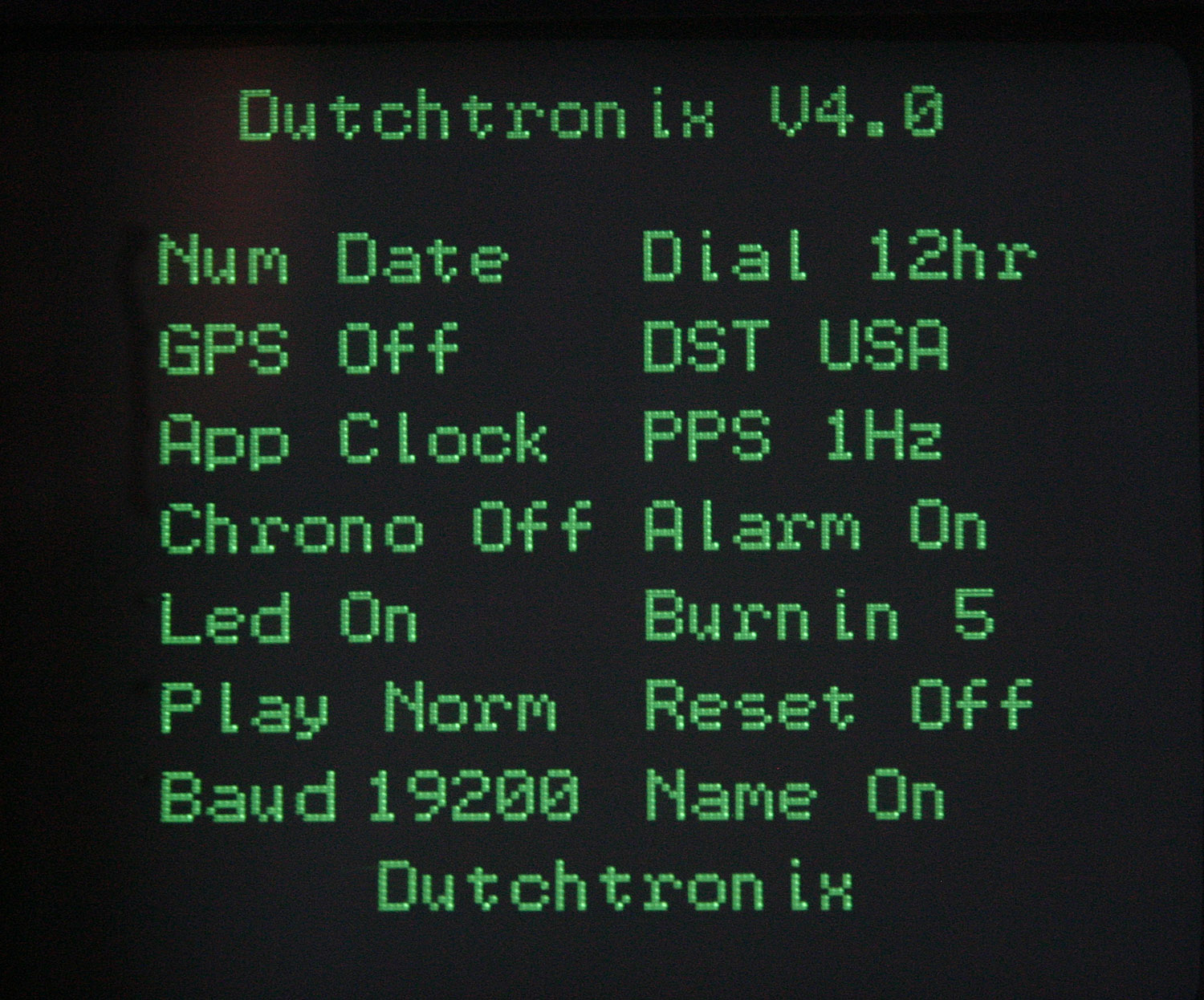
Q: What options are available
using the on-screen menu?
A: An S1 short push will enter the Menu
Mode. Once the Menu mode is entered, you'll see the following menu on the
screen:
|
Option |
Values |
Function |
Option |
Value |
Function |
|
Num |
12hr |
Select Numeric Field to Display |
Dial |
12hr |
Select Clock Dial to Display |
|
GPS |
Off |
Select GPS NMEA input using the selected local time zone offset |
DST |
USA |
Select Automatic |
|
App |
Clock Cal Term Gen Demo Boot |
Select application to run |
PPS |
1Hz 4096Hz -4.. +4 |
Set PPS mode and apply software accuracy correction. |
|
Chrono |
Off |
fractional seconds |
Alarm |
Off |
Turn Alarm function On and Off |
|
Led |
On |
Controls on-board Led |
BurnIn |
0.. |
Control Burnin Prevention frequency |
|
Play |
Off |
Fun modes: Reverse, Fast Forward and Fast Reverse |
Reset |
Off |
Re-initialize the EEProm area of the Atmega328p to "virgin" state. |
|
Baud |
19200.. |
Set Baud Rate on Serial Interface |
Name | On
Off Edit Day Debt |
User Name Display
or |
| Current User Name is displayed below the Menu |
Q: How do I change an option on the AVR Clock using the S1 button switch?
A: An S1 short push will enter the Menu Mode. The option being updated/selected is flashing. Move to the next option by an S2 short push. The options are selection values. An S1 short push will show the next selection value; keep S1 pushed to auto-repeat. Moving to the next option (using an S2 short push) when the selection value has changed, will activate the selected value and the clock will leave the menu mode. Menu mode times out after 30 seconds of inactivity.
Q: What does the the S2 button switch do?
A: A short S2 push will display a help screen for about 5 seconds, or until the user hits another short S2 push. The S2 switch will reboot the AVR Oscilloscope clock when doing a long push. Use an S2 long push if you want to leave the menu quickly. When in Time/Date Change mode or on the Menu page, the S2 short push moves the cursor from field to field. This allows you to move very quickly through the menu. Finally, when the Alarm is activated as shown in a flashing dial, a short S2 push will stop the Alarm.
Q: How do I tell the AVR clock to display only the analog clock?
A: Select the Num option, set the value to Off. This mode is persistent.
Q: How do I tell the AVR clock to display a minimal dial on the analog clock?
A: Select the Dial option, set the value to Min. Only 4 hour numbers will be displayed. This mode is persistent.
Q: How do I tell the AVR clock to display a dial with Roman Numerals on the analog clock?
A: Select the Dial option, set the value to Rom. Roman Numerals will be now be displayed on the dial. This mode is persistent.
Q: How do I tell the AVR clock to show a Digital Clock Display ?
A: Select the Dial option, set the value to Dig. The time will be displayed in 24 hr format using large digits. There will also be a dial of dots, one of which will be highlighted to show the current second value. IOCTL bits are available to fine-tune this display. This mode is persistent.
Q: How do I tell the AVR clock to show a Binary Clock Display ?
A: Select the Menu-Dial option, set the value to Bin. The clock will switch to a Binary Clock Display. This clock will display 24 Hour time in a BCD Binary fashion. You will see 6 columns displaying from 2 to 4 on-off "lights". The left-most 2 columns show the hours, the middle 2 columns show the minutes and the right-most columns show the seconds. Each column represents one digit, together they form a value. The lowest position in each columns represents bit 0, the highest can be bit 2, 3 or 4. The size of each column was selected to represent the full range for each digit in its position. For example, the lowest digits for seconds can range from 0..9 so we need 4 bits to display the number 9 in binary. The highest digit for hours can range from 0..2 so we only need 2 bits to display the number 2 in binary. When you select a hexadecimal Numeric Display (Menu-Num: Hex) with this Binary Clock Display, you are looking at a Bi-Hex clock. This mode is persistent.
Q: How do I read the Numeric Time in Hex?
A: The Numeric Time in Hex is a binary representation of the values of the time components, in 24 hr format. Convert each field from hexadecimal to decimal (0..59) and you'll see the current time. There is no separate BCD Hex Numeric Display since such a display is identical to the regular 24 hr Numeric Display since each digit is in the range 0..9 (identical in decimal and hex)
Q: How do I tell the AVR clock to display the Numeric Display in AM/PM mode?
A: Select the Num option, set the value to 12hr. This mode is persistent.
Q: How do I change the Clock Face to something more serene?
A: The AVR clock provides 3 different controls to change the clock face, providing a total of 30 different combinations. Use the Num option to turn the numeric display Off . Use the Menu-Dial:Min option to remove most digits from the clock face. The combination of no numeric display and fewer digits provides a minimal but elegant display. You can select the Numeric Display format with the Num option, value 12hr, 24hr, Hex, Date, or Off
Q: What is PPS and how do I change the PPS frequency?
A: PPS refers to "Pulse per Second". The Real Time Clock (RTC) interrupts the AVR at precise intervals. The AVR keeps track of time by counting these pulses. By default, the Dutchtronix AVR clock runs in 1Hz PPS mode. This mode can also be used when using an external signal to advance the time, for example using a GPS device based 1PPS (1 pulse per second) signal.
However, it may be possible, depending on the particular crystal used and ambient temperature, that your clock runs more accurately when the RTC interrupts the AVR 4096 times per second. After 4096 pulses, 1 second has elapsed. Only experimentation can tell.
When changing between 1Hz and 4096Hz PPS mode, the RTC is also reprogrammed to generate the corresponding pulse frequency.
When using an external signal, the shunt on the 1PPS header needs to be removed and the external signal needs to be connected to the left pin of the 1 PPS header, and an appropriate GND pin.
Keep in mind that the 4096Hz PPS mode will require a little bit more power from the backup battery when the clock is turned off, than the 1Hz PPS mode.
The values -4 to +4 are used to apply a software time accuracy correction, see the next entry.
Q: How do I change the accuracy of the AVR Clock using the PPS field?
A: It is possible to apply a software accuracy correction using the PPS field. What this means is that the clock must be fed a 4096Hz pulse signal from the RTC (or some external signal) but NOT a 1Hz signal. The AVR will internally use a different count to determine when a second has passed based on the following table:
| PPS Value | AVR Count | result | result |
|
-4 |
4092 |
run 0.097656% faster |
3.52 sec/hour faster |
|
-3 |
4093 |
run 0.073242% faster |
2.64 sec/hour faster |
|
-2 |
4094 |
run 0.048828% faster |
1.75 sec/hour faster |
|
-1 |
4095 |
run 0.024414% faster |
0.88 sec/hour faster |
|
1 |
4097 |
run 0.024414% slower |
0.88 sec/hour slower |
|
2 |
4098 |
run 0.048828% slower |
1.75 sec/hour slower |
|
3 |
4099 |
run 0.073242% slower |
2.64 sec/hour slower |
|
4 |
4100 |
run 0.097656% slower |
3.52 sec/hour slower |
If you find that the clock runs 1 second per hour too fast, select PPS option 1; this will slow the clock down by about 1 second per hour.
Keep in mind that the correction is only applied when the clock has power. When the power is turned off, the Real Time Clock maintains time using the on-board battery and NO correction can be applied.
Q: How do I change the User Name to my own preference?
A: The current User Name is displayed at the bottom off the menu page, but is not a normally selectable field. Select the "Edit" option in the "Name" field to change the User Name. The actual edit process, once a User Name edit has started, is simple: the character being changed flashes. An S1 short push "increases" the char in an ASCII sequence (ASCII 127 is the highest char available, after which rotation to SPACE (ascii 32) occurs; keep S1 pushed to auto-repeat.
An S2 short push advances to the next char in the name. Two spaces in a row complete the edit. For example to change the user name to "John Doe", enter "John Doe ". This method allows for single spaces inside a name. The maximum length of a name is 20 positions. Editing will stop once the 20 positions have been reached.
If you are impatient like I am, you will be happy to know that as of firmware V3.5, auto-repeat is supported when changing a name. Very nice if you just pushed the button one too many times, and ended up with the next character!
The desired User Name is stored in the AVR EEprom memory. Flashing (aka blinking) may obscure the current char for a very short time (1/2 second) so be patient when incrementing a character: use the S1 auto-repeat feature to get close to the desired character value, then use S1 short pushes for the last stretch.
If you entered the edit mode by accident, you can either advance to the end of the name using S2 short pushes, followed by 2 spaces, do an S2 long push to reboot the clock or you can just wait 30 seconds and the clock will time-out the edit mode.
Display of the User Name can be turned off using the "Off" option the "Name" field.
Q: How do I make the AVR Clock show the "Day of the Week"?
A: Select the Name option, set the value of Day. This mode is persistant. Note that this replaces the current User Name. Select Menu-Name:On to show the User Name again.
Q: How do I make the AVR Clock show the current Debt of the US government?
A: Select the Name option, set the value of Debt. The Debt amount is updated every minute. This mode is persistant. Note that this replaces the current User Name. Select Menu-Name:On to show the User Name again.
Q: What is the "Automatic Daylight Saving Time" feature all about?
A: Daylight Saving Time, called "Summertime" in the European Union, is a time system where time is advanced by one hour sometime early in the year and time is set back one hour near the end of the year (in the Northern Hemisphere.) When you live in the USA or Western Europe, you won't have to change the clock to correct for Daylight Saving Time (DST) until 2021! The dates when DST takes effect and ends are programmed in the AVR clock for the years 2015-2021, based on the most recent laws, both for the USA and the European Union.
Not only will the clock automatically set the time one hour forward (and one hour back) when transitioning in and out of a DST window (the combination of date and time for which DST is active), the clock will also set itself to the proper time if it has been turned off for a while. Even though the Real Time Clock (RTC) on the AVR clock keeps running when the clock is turned off, it is not aware of DST so the RTC time will be off by one hour if it was turned off before a DST window, then turned on within such a window. The AVR clocks make the necessary adjustment when turned on. The clock keeps track of the adjustments made for each of the 7 supported years so that adjustments (forward and backward) are only applied once.
If the user manually changes the date, the clock will check if this new date requires a DST adjustment and will do so, if needed.
If the user manually changes the time, the clock assumes the user knows best, will not do an DST adjustment but will mark that a DST adjustment was made for the current year (if appropriate).
The time at which DST starts and ends is fixed at 2:00 AM. This is valid for the USA and most of Western Europe. However in the United Kingdom (which has UTC time), DST starts and ends at 1:00AM. There is no separate UK zone so the AVR clock is not 100% accurate for those living in the United Kingdom.
The automatic DST feature also works with the GPS NMEA input mode, again assuring you accurate date and time. Combine GPS NMEA input mode with Automatic Daylight Saving Time and you'll have the correct date and time until March 8, 2021, 01:59 AM, accurate to within 10 milliseconds (when also using the GPS 1 PPS input.)
Q: What does the "Chrono" Menu option do?
A: The Chrono option in the menu enables a fractional seconds display in the 24 hrs and hexadecimal numeric display modes. This fractional seconds display shows the current time in 1/100 of a second increments.
Q: Why does the clock display jump ever so slightly on some minutes transitions?
A: The AVR clock offsets the display slightly every 5 minutes (by default) to prevent screen burn-in on your oscilloscope. You can change the frequency of this burn-in prevention feature to be from 1 to 9 minutes using the Burnin option, value 1 to 9. Select value 0 to turn off Burn-in prevention completely. This mode is persistent.
Q: What does “this mode is persistent” mean?
A: It means that the mode is remembered when the power is turned off, and the clock will start in the same mode when the power is turned back on. This is achieved by setting status bits in the EEProm section of the Atmega AVR.
Q: How do I align the clock properly on my scope?
A: a Calibration screen is available for this purpose. Select the App option, set the value to Cal , which will display a Calibration Pattern on the scope, to adjust the display. While in Calibration Mode, use the Volts/Div VAR knobs together with the position knobs to get the best square possible; this screen can also be used to fine-tune the probe compensation adjustments. Get back in the Menu mode (S1 short push), Select the App option, set the value to Clock , to return to the normal clock display.
Q: Why doesn’t the Calibration Screen change location to prevent Burn-in?
A: This is a design decision. Having the Calibration Screen move while you are aligning the screen doesn’t seem to be a good idea.
Q: How do I tell the AVR clock to start and stop blinking the LED?
A: Select the Led option, set the value to On or Off to toggle the LED blinking. Stopping the blinking LED will also suppress the valid NMEA record received notification on the display ('G') if GPS mode is enabled. This mode is persistent.
Q: How do I tell the AVR clock to show the current time in Morse code using the LED?
A: Select the Led option, set the value to Morse. The LED will show the current time using Morse code. The actual sequence transmitted is: "CT hh:mm:ss". The Morse sequence may take up to 22 seconds, after which the process repeats, each time using the current time.
Q: How do I reset the AVR clock without disconnecting power?
A: An S2 long push will reboot the AVR clock. Shorting pins 5 (Reset, active low) and 6 (GND) of the ISP connector will hardware reset the AVR clock. Normally, no connector is present on your board, but you can solder in a 2-pin header. There are 5 columns of 2 pins each; use the middle column.
Q: Is there another way to communicate with the AVR Clock?
A: Yes, you can also use the serial interface to communicate with the AVR Clock. This requires a standard Serial cable with DB-9 connectors and a terminal, usually a terminal program on a computer. Use the letter "x" to obtain a prompt. This interface is completely optional.
Q: How do I know which version of the firmware my clock is running?
A: Enter Menu mode using a S1 short push or the Help screen using a short S2 push. The top line shows the current firmware version. The serial connection will also display the firmware version, both when starting up and when using the status command ("s").
Using an External Clock Source
Q: How do I apply an external clock source to the AVR clock?
A: The AVR clock normally receives a 1 PPS (Pulse per Second) signal from the Real Time Clock (RTC) and triggers on the negative going edge. This pulse can be intercepted and replaced at the header marked "1PPS". The "1PPS" pins are normally shorted by a shorting block, but you can feed your own 1 PPS signal to the left pin of the 1PPS header (closest to the corner).
Q: How do I hook up the AVR Clock to my GPS unit?
A: Connecting your GPS unit to the AVR Clock is simple once you get the correct cabling. This step may be frustrating though.
|
You can use the built-in Terminal application, already present on the AVR Clock (Menu-App: Term), to test out the serial communication between a GPS device and the AVR oscilloscope hardware! Don't forget the set the proper baudrate in the menu (Menu-Baud:4800.) Once the connection is working, configure the GPS unit to send out NMEA $GPRMC records at 4800bps; this is the default on most units.
The GPS device may send out lots of NMEA information every second. The AVR clock will have to process every record, discarding most of them. Even though the Serial Input on the AVR Clock is completely interrupt driven and buffered, it does take some time to find the individual NMEA records, time during which the oscilloscope screen cannot be refreshed and you may see an intensified dot on the screen when a lot of unwanted NMEA records are streamed by the GPS unit. If possible, disable the sending of other records and set the send frequency of the $GPRMC record to no more than once every 5 seconds; this is not required but makes it easier for the AVR Clock. If necessary, also select UTC time, not GPS time. Do not connect the cable to the AVR Clock yet at this point.
Start the menu on the AVR Clock and advance to the "GPS" field. The default value is "Off". S1 short pushes will cycle you through the possible options; keep S1 pushed for auto-repeat. These numbers indicate your "local time zone offset" from UTC (Greenwich time). For example, the local time zone offset here in the Northwest is -8. For the United Kingdom, the offset is 0. Activate the selected option and connect the cable. If all is well, you will see the letter 'G' appear in the status field every 4 to 5 seconds, lasting 1 second. This indicates that the AVR clock has found a valid $GPRMC record. The 4 to 5 seconds is because the AVR clock will wait 4 seconds after finding a valid $GPRMC record before accepting another one. Parsing these records costs time, including several ASCII to binary conversions, so the AVR Clock waits 4 seconds after receiving a valid record. If the AVR clock determines that its time and/or date differs from the time and/or from the GPS device (after adjustments for the local time zone offset and possibly Daylight Saving Time), it will update itself and start a 5 second warning (flashing 'G'). This should be infrequent. The display of a 'G' every time the AVR Clock receives a valid $GPRMC record can be turned off using the Menu-Led:Off option.
Please disconnect the GPS cable before changing the "GPS" field in the AVR Clock menu to "Off". First of all the baud rate of the serial port is changed to its original value and secondly, the AVR clock will try to interpret the incoming data (from the GPS device) as commands.
Combining the 1PPS signal from a GPS unit with NMEA parsing will give you an extremely accurate clock which will continue running even if you lose the GPS satellite signal (displaying the 'P' warning); the clock will correct itself, if necessary, once another lock is obtained.
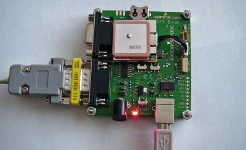
SparkFun Electronics kindly made one of their current GPS units, the amazing EM406a Sirf III from USGlobalSat, available for testing and I'm glad to report that it works like a charm, inside, no external antenna required, no configuration required. Here is my setup:
|
I used the the GPS Evaluation board from SparkFun Electronics and installed the EM406a. This board can be powered from a USB connection. To connect this setup to the AVR Clock, I used a male to male DB9 gender changer together with a custom AVR Clock serial cable but changed to a cross-over cable by swapping the crimp pin connectors (pin 2 and 3) in the terminal housing. If you make your own gender changer using 2 male DB-9 connectors, you can cross the wires between pins 2 and 3 to get the cross-over effect. You can also use a NULL modem adapter.
Use the excellent USGlobalSat demonstration software to check the GPS unit and configure the NMEA output to one $GPRMC record every 5 seconds (or less frequently) at 4800bps (this is not required; the default configuration works out of the box). |
|
Q: Do I need the use the Serial Interface?
A: No, use of the Serial Interface is optional. The Dutchtronix AVR oscilloscope scope clock uses the on-board push button switches S1 and S2 to set the time and has an on-screen menu to set options, using the same switches.
Q: What is the hardware connection between the AVR clock and the RS-232 interface on the computer?
A: You can use a standard serial cable. Such a cable has one female DB-9 connector and one male DB-9 connector. The male DB-9 connector plugs into the female DB-9 connector on the clock. These cables also connect the proper RX and TX pins on each side of the cable.
You can also make a custom cable consisting of a female DB-9 connector (for most PCs) and a 3-pin connector (not included with the clock kit). Wiring is as follows:
3-pin connector - 1:GND, 2:out/RXpc, 3:in/TXpc.
DB-9 connector - 5:GND, 2:RX, 3:TX.
Pin 1 of the 3-pin polarized header on the PCB is the rightmost pin.
Q: What baud rate do I set for the Serial interface to my computer (or some other terminal)?
A: The AVR clock uses a default baud rate of 19,200. Other values are default (8 bits, 1 stop bit, no parity, and no handshaking). You can change the baud rate using the on-screen menu.
Q: How do I change the baud rate on the Serial Interface?
A: Use the on-screen menu (S1 short push) to change the baud rate: Menu-Baud:value. Supported values are 19200 (default), 28800, 38400, 57600, 115200, 250000, 4800, 9600, 14400. The AVR Clock will remember the current baud rate and automatically set the baud rate to 4800 bps when enabling GPS input mode but you can then change it to another value, if so desired. The AVR Clock will restore the remembered baud rate when disabling GPS input mode. The selected baud rate value is persistent, meaning the value is retained after a reboot or power cycle.
Q: How can I check the current baud rate setting on the Serial Interface?
A: Select the on-screen menu (S1 short push) and the current baud rate is shown in the field called "Baud"). Use S2 short pushes to quickly exit the menu.
Q: How do I communicate with the AVR clock using the Serial interface?
A: Using the proper serial cable, as described above, you can use your favorite terminal program, such as HyperTerminal or Bray’s Terminal, and set it to use a 19,200 baud rate, 8 char, 1 stop, no parity, and no handshaking (default baud rate). Make sure you select the proper COM port, where the cable is plugged in, usually COM1. If the connection is good, the AVR clock will display a sign-on message when it starts. You can communicate by using the ‘x’ key. The AVR clock will show a command prompt with all available commands. Type 'h' for more details. All command keys can be either upper or lower case; the AVR clock will treat them as identical. Prompts will time out after 30 seconds.
Note that the Serial Command Line interface is not available when the GPS NMEA parsing option is enabled since that feature uses the same serial port. The same applies when running other applications like the Dutchtronix Terminal or the miniDDS function generator since these applications use the serial ports themselves.
Q: How do I send commands to the AVR clock using HyperTerminal?
A: HyperTerminal sends each character typed immediately to the AVR clock, which will prompt you for the next character, if needed. You can always type another ‘X’ to cancel a command. Please double check that hardware handshaking is turned off because it is the default in HyperTerminal.
Q: How do I send commands to the AVR clock using Bray’s Terminal?
A: Bray’s Terminal does not send each character typed immediately, as HyperTerminal does. You must select the white “send” line near the bottom of the window (transmit section) with the mouse and type the characters to send there. Do not add any CR or LF characters. Use the “send” button to transmit the characters, one at a time or all at once, whatever you prefer. The AVR Clock can buffer up to 128 characters at a time. For example to change the clock to 2PM, you can type “XT140000” in the send line and then hit the ->send button.
Bray’s Terminal also allows you to assign macros containing multiple characters. If you use those, you can send multiple commands in rapid succession. You’ll see that the AVR clock is incredibly responsive without affecting the display.
Q: Can I send commands to the AVR clock any other way?
A: Sure, you can use the "copy" command in a DOS box to control the clock. For example, you can make a script to pull the current time from the internet (using an NTP server), create a text file with a clock command and send that file to the AVR clock to set the time, like this:
copy settime.txt com1:
Where settime.txt would look like this:
xt12:00:00
Using this technique, you can also use the AVR clock to display a text based slide show. Check out the file below for an example
Please note that there are trailing spaces in the files line1.txt to line7.txt
Q: My laptop does not provide an Serial interface. What can I do?
A: The best solution for the Dutchtronix hardware 3.1 board is to install the components for the optional USB interface on the AVR Clock PCB. Note that these components are Surface Mount devices. The following components are required:
|
One thing to keep in mind with the USB interface is the fact that you will need to communicate with a USB Host, usually a computer. The USB interface cannot be used to communicate with another USB client (aka slave), unless you use some kind of bridging device. A USB only GPS device cannot be directly interfaced; use a serial GPS receiver instead.
The use of the RS-232 interface is optional. It can be used for firmware upgrades, a very fast user interface, GPS device input and other applications, e.g. the built-in Terminal Application which now supports Persistent Vector Graphics, allowing you to play a game like Asteroids using your oscilloscope. As an alternative, you can use an external USB-Serial converter. Connect this converter to the middle pins of the TXROUTE and RXROUTE headers if it expects TTL levels on the serial pins, use the DB-9 or RS-232 polarized header if it expects RS-232 levels.
Q: If my oscilloscope is not near my computer, what should I do?
If you want to use the serial interface away from your oscilloscope, you can disconnect the AVR clock from the oscilloscope and check its operation near the computer independently (except for the Calibration Screen). The LED on the AVR clock will, by default, blink every second if it is operating properly, or it will show the current time in Morse code if that option was selected in the Menu. The AVR clock will also communicate its status through the RS-232 interface; you don’t need a hookup to an oscilloscope to change settings using the serial interface.
Q: What commands are available using the Serial interface?
A: Once the cable is connected properly, the clock will display a sign-on message on the terminal when it powers up. The command 'X' is used to get the clock's attention (interactive mode). A prompt will show:
Command(A,B,C,D,F,G,H,I,J,K,L,M,N,P,R,S,T,U,V,W):
A: Change Application (Clock, Calibrate, Term, Func, Demo, Boot).
B: Change Burn-in Prevention Frequency
C: Toggle Alarm
D: Set Date
F: Set Clock Face Mode
G: Toggle GPS NMEA input Parsing
Currently it is not possible to set the Time Zone Offset in command
mode.
H: Show extended Help
I: Set IOCLT customization word
J: Set Name Display Mode
K: Toggle the Fractional Seconds Display
L: Set LED Mode
M: Toggle 1PPS Trigger Mode
N: Set Numeric Display Mode
P: Set Clock Play Mode
R: Reset the EEProm Configuration Data
S: Show Status info
T: Set Time
U: Set Automatic Daylight Saving Time Adjustment
V: Toggle Verbose Output
W: Enter User Name
Currently it is not possible to select the "Day of the Week" option in command mode
Execution of any of these commands, or another 'X' will end the interactive mode. Prompts will time out after 30 seconds. Note that the commands can be given in either upper or lower case.
Q: How do I tell the AVR clock to change the Clock Face?
A: Use the 'F' command followed by a 1 digit numeric value.
The full list of options is:
0 12 hr dial
1 24 hr dial
(can show numbers 13..23 on the dial)
2 Roman Numerals
Dial
3 Digital Clock
Display
4 Binary Clock
Display
5 Minimal dial
Q: How do I tell the AVR clock to change the Numeric Display?
A: Use the 'N' command followed by a 1 digit numeric value.
The full list of options is:
0 12 hr
(AM-PM)
1 24 hr (International/Military
Time)
2 Hexadecimal
3 Date
4 Alarm
5 No Numeric Field
Q: How do I tell the AVR clock to display just the dial on the analog clock?
A: Use the ‘F5’ command to select a dial with just 4 numbers. This mode is persistent.
Q: How do I tell the AVR clock to display the Numeric Display in AM/PM mode?
A: Use the ‘N0’ command to set the Numeric Display to AM/PM mode. This mode is persistent.
Q: How do I tell the AVR clock to start and stop blinking the LED?
A: Use the ‘L’ command followed by a 1 digit numeric value to control the LED.
The full list of options is:
0 turn LED blinking ON
1 make LED show the current time using Morse code
2 make LED show debug information, specifically when serial input buffer overflow occurs
3 turn LED blinking OFF
Turning the LED off will also suppress the 'G' notifications on the screen when a valid $GPRMC record has been received (in GPS mode). This mode is persistent.
Q: How do I tell the AVR clock to send the current time and date to the Serial interface every minute?
A: Use the ‘V’ command to toggle Verbose mode. This mode is persistent.
Q: How do I align the clock properly on my scope?
A: Select the Calibration Mode, command "A1", which will toggle between the regular clock and a Calibration Pattern on the scope, to adjust the display. While in Calibration Mode, use the Volts/Div VAR knobs together with the position knobs to get the best square possible; this screen can also be used to fine-tune the probe compensation adjustments. use command "A0" to get the clock mode back.
Q: How do I set the time on the AVR clock using the Serial interface
A: Type ‘X’ on the terminal. Once you get a command prompt, type ‘T’. The AVR clock will prompt you for the time. The hours info must be entered in the 24-hour format. Here is the conversion from the US standard to 24-hour format:
|
US Regular Time |
24 Hour Time |
US Regular Time |
24 Hour Time |
|
12:00 a.m. |
00:00 |
12:00 p.m. |
12:00 |
|
1:00 a.m. |
01:00 |
1:00 p.m. |
13:00 |
|
2:00 a.m. |
02:00 |
2:00 p.m. |
14:00 |
|
3:00 a.m. |
03:00 |
3:00 p.m. |
15:00 |
|
4:00 a.m. |
04:00 |
4:00 p.m. |
16:00 |
|
5:00 a.m. |
05:00 |
5:00 p.m. |
17:00 |
|
6:00 a.m. |
06:00 |
6:00 p.m. |
18:00 |
|
7:00 a.m. |
07:00 |
7:00 p.m. |
19:00 |
|
8:00 a.m. |
08:00 |
8:00 p.m. |
20:00 |
|
9:00 a.m. |
09:00 |
9:00 p.m. |
21:00 |
|
10:00 a.m. |
10:00 |
10:00 p.m. |
22:00 |
|
11:00 a.m. |
11:00 |
11:00 p.m. |
23:00 |
You can also send the new time in one command, for example 'xt130000 will set the time to 1:00 PM
Q: How do I change the Clock Face to something more serene?
A: The AVR clock provides 3 different controls to change the clock face, providing a total of 37 different combinations. Use the ‘N’ command to select the Numeric Display mode (0-5). Use the ‘F’ command to select the Dial Display mode (0-5).
The combination of No Numeric Display and Minimal dial (XN5XF5) provides an serene display.
Q: How do I change the Triggering
method for the 1PPS signal?
A: The AVR triggers by default (when in a clean state) on the falling edge
of the 1PPS signal because the Real Time Clock, which is the default 1PPS signal generator,
produces a negative going signal. An external 1PPS signal may require a trigger
on the rising edge of the signal, for example if it is a long positive going
signal or the return to GND level is very slow. You can toggle the 1PPS trigger
mode using the 'M' command. The AVR Clock will reboot after this command since
the INT0 interrupt needs to be reinitialized.
Q: How do enter a User Name using the Serial Interface?
A: Use the 'W' command. You will be prompted for a the name. Enter the desired name followed by 2 spaces, a CR, an LF or use all 20 available characters. Trailing spaces will automatically be removed.
Q: How do I change application using the Serial Interface?
A: Use the 'A' command. You will be prompted for a 1 digit value (0..5). 0 selects the Clock application, 1 the Calibration Mode, 2 the Terminal application, 3 the Function Generator application, 4 the Demo mode and 5 reboots the clock.
Q: What does the IOCTL option do?
A: IOCTL is a short hand for IO Control, a term used to name a control word. Using the IOCTL it is possible to customize the clock more. The customizations provided are pretty rare and no separate menu entries are available for them. Each option is either ON or OFF, indicated by a bit in the 16-bit IOCTL word. To change the IOCTL word, use the 'I' command, followed by 4 hex digits; all 4 digits are required. For example to set bit 2, enter "XI0004"; to set bits 2 and 3, enter "XI000C". There are currently 7 options available:
|
IOCTL_NODIALDOTS |
bit 2 (0x0004) | Do not show a moving dot in the Digital Clock Face |
|
IOCTL_12HRDIG |
bit 3 (0x0008) | Show time in Digital Clock Face as a 12 hour clock |
|
IOCTL_NUMOFFTERM |
bit 4 (0x0010) | Do not show Numeric Field in Terminal |
|
IOCTL_USRNAMETERM |
bit 5 (0x0020) | Show Name Field in Terminal, not Numeric Field |
|
IOCTL_BURNINTERM |
bit 6 (0x0040) | Allow Burn-in prevention in Terminal |
|
IOCTL_SECSDEBTMODE |
bit 8 (0x0100) | Update the Debt value every second. |
| IOCTL_AUTODEMOMODE | bit 9 (0x0200) | Clock starts DEMO mode automatically after 10 minutes of no interaction |
Q: What is the 'DEBT' option about?
A: If you feel the need to see some depressing information, select the 'DEBT' option in the "NAME" field using the on screen Menu. This is a persistent option.
Q: Why can't I use the Serial Interface when the AVR Clock is in Terminal Mode?
A: Because the Terminal Mode uses the Serial Interface.
Q: Why can't I use the Serial Interface when the GPS mode is active?
A: Because the AVR Clock uses the Serial Interface to communicate with the GPS device.
Q: Why can't I use the Serial Interface when the Clock Menu is active?
A: Because the Clock Menu and the Serial Commands would want to change the clock settings simultaneously.
Q: Why is there is a flashing B on my clock?
A: The RTC has reported a Low Battery. Please power cycle the clock to check if it happens again. The next step is to test the actual backup battery voltage with the power turned off. If it looks ok (2-3V), you can clear the flag in the RTC by explicitly updating the time (S1 long push) and restarting the clock (S2 long push). If the battery voltage is too low (<1V), you’ll have to change the Lithium backup battery. The original battery is a Renata CR1225FV, Mouser part number 614-CR1225FV-LF; however, any 3V Lithium battery will work, provided you connect it properly. This Battery warning also implies that the clock time may no longer be accurate. This warning will automatically stop after 60 seconds.
Q: Why does the AVR clock display a flashing letter P?
A: This happens when the AVR clock is in back-up mode, i.e., it does not receive the 1 PPS signal (1 Pulse per Second) from the RTC (or another external source). The AVR clock has a countdown timer that is activated after roughly 1 1/30 second (based on its own crystal oscillator), and it advances the time if no PPS signal was received.
Unless you provide your own 1PPS signal from a GPS device, make sure you installed a shunt on the 1PPS pins because this shunt connects the 1PPS signal from the Real Time Clock to the AVR processor.
When providing your own 1PPS signal, this flashing P will most likely happen when the GPS device looses its satellite lock. The clock will keep going in that case, though running a little slow. If you have the NMEA output of the GPS device connected to the Serial Port (and the GPS option is selected with the proper local time zone offset), the AVR clock will automatically set the proper time and date once the GPS device gets another lock. A flashing letter "G" indicates the the time or date was changed based on the incoming NMEA records.
The RTC has its own backup battery and is always powered. To reset the RTC, please remove it from its socket and reinsert it (with the power disconnected, of course) The time and date will be random if this happens, so please Reset the EEProm configuration data or set the correct time and date immediately.
Q: Why does the AVR clock display a flashing letter G?
A: This happens when the AVR clock determines that its time and/or date is different from the time/date obtained from the NMEA output of a GPS device connected to the Serial Port (and the GPS option is selected with the proper local time zone offset). The AVR clock will update its time (and the on board Real Time Clock) to the time/date obtained from the GPS device and will display a flashing letter "G" for 5 seconds.
Q: Why does the AVR clock display the letter G once?
A: This only applies when the NMEA output from a GPS device is connected to the Serial Port and the GPS option in the menu is enabled. When the AVR clock receives valid NMEA data from the GPS device (but no more frequent than once every 5 seconds), it will display the letter G for 1 second.
Q: How do I run one of the other preloaded applications ?
A: Select the menu (S1 short push), move to the "App" field (S2 short push), advance to the application of your choice (S1 short push) and activate it (S2 short push). You can choose from Terminal ("Term"), Calibration Screen ("Cal"), Function Generator ("Gen"), Clock ("Clock"), Demo ("Demo") or reboot the AVR clock ("Boot").
Q: How do I exit the other applications?
A: When running the terminal program, just select the menu again (S1 short push) and go to one of the other apps, as described above. From the Function Generator, you must power cycle the board. Trick: pushing S2 while sending data using the DDSControl program will also reboot the AVR clock.
Q: Which application runs when the Clock board starts up?
A: The Clock and Terminal application are persistent, meaning the board will start them again after a reboot (incl. a power cycle.) The Function Generator application is not persistent since the only way to exit it is through a reboot (incl. a power cycle.)
Q: How do I use the Terminal Application?
A: Please read this page.
Q: How do I use the Function Generation Application?
A: Please read this page.
Q: How do I reboot the AVR clock from the menu?
A: The "App" field has a choice "boot" which will reboot the AVR clock when selected. You can also do a long push on switch S2 to reboot at any time.
Q: Will the clock lose time when running one of the other applications?
A: No, the internal time tracking mechanism is active for all applications except the Function Generator. The on-board Real Time Clock (RTC) keeps accurate time while the Function Generator is running; The AVR Clock will reload the current time from this RTC when starting the clock application again.
AVR Clock hardware features:
The main hardware features of the AVR Clock boards are:
|
Equipped with the Atmega328p AVR, providing twice the code space and memory of the Atmega168 used in earlier versions. | |
|
Use of the Analog Devices AD7302 DAC with built-in OpAmp. This DAC has low output impedance while generating an excellent image. The low output impedance allows the use of regular BNC cables or even wires to connect the Clock board to a display device like an oscilloscope, an X-Y monitor or even a home made CRT device. Probes are still supported. | |
|
On board power supply. Allows the use of an 8-15V wall wart with a standard DC connector (5.5mm outside diameter Barrel Jack, center positive) to power the AVR Oscilloscope Clock. A LED indicates the presence of power and there is an On-Off switch. A separate 5V connector is present too. | |
|
Two on-board BNC connectors for use with standard BNC cables. Probe connectors (“turret terminals”) are present in the form of 2mm copper wire. | |
|
On board trimpot to set the output voltage range of the DAC. Maximum voltage range is 5V. | |
|
Intensity control is present with both positive (Z) and negative (ZINV) drive levels. | |
|
True RS-232 level Serial Interface with DB-9 female connector using a MAX232A compatible IC. This allows you to connect the AVR Oscilloscope Clock to a computer using a standard serial cable. Since the level converter is truly RS-232 compliant, you can also connect the AVR Oscilloscope clock to an electronics project that uses a parasitic level converter, using the built-in terminal application. | |
|
Direct access to the AVR serial interface, for those times you need to do serial communication at the 5V (TTL) level. | |
|
Lots of capacitors for reliability. | |
|
Support for a USB connection using a standard USB cable. With the optional USB connection parts installed you can even power the AVR Oscilloscope clock from the USB connection. |
This AVR clock is able to run firmware V4.0 and above.
Image quality varies from scope to scope of course. X-Y monitors, which are like oscilloscopes but without the time-base section, work best. All pictures showing the Dutchtronix AVR Oscilloscope clock with V4.0 firmware were taken on a Tektronix 608 X-Y monitor using the Intensity Control output ('Z') available on the board.
Q: Why are there 3 pins on the connector marked Ground?
A: These three pins are all three Ground. They are there to give you more freedom hooking up ground wires.
Q: The clock dial and or digits seem distorted. Is there a way to fix this?
A: This can happen if you are using 10x probes and the probes aren't properly compensated for your scope. Find the adjustment screws on each probe and adjust them until the image is clean. This should not happen with 1X probes or direct wires (incl. BNC cables)
Q: How does the AVR clock trigger on the 1 PPS signal?
A: By default the AVR clock uses a 1PPS signal generated by the on-board RTC. This is a negative going pulse so the AVR clock triggers on the negative going edge. Most GPS units have a TIMEKEEP signal that is normally low and pulses high for 200 mSecs every second; by default, the AVR clock triggers on the negative edge at the end of this pulse. You can use the Serial Command 'M' to toggle the trigger mode of the AVR clock.
Please note the following. The AVR Clock has an internal pull-up resistor enabled on this pin so that the pin is HIGH when not connected (e.g., when the shunt is removed from JP6). If your 1 PPS signal is normally low, it will have to PULL DOWN the signal to LOW, and a small current will run from the AVR to your signal source.
Q: What is the purpose of the push button switches S1 and S2 on the AVR clock?
A: It is the user input interface. As S1 short push will enter the Menu mode. An S1 long Push will enter the Change Mode. An S2 short push will display the Help Screen. The S1 push button switch is also used to allow firmware upgrades using your PC (see firmware upgrade).
Q: What is the purpose of the ‘Z’ pin on the AVR clock?
A: The Z (Intensity) output on the AVR clock dims the beam at the appropriate moments. This output will decrease its voltage towards 5V to decrease the scope intensity. Please connect this signal to your oscilloscope intensity control input, if present. It is very effective in suppressing highlighted dots on the screen.
Q: What is the purpose of the ‘ZINV’ pin on the AVR clock?
A: The ZINV (Inverted Intensity) output on the AVR clock dims the beam at the appropriate moments. This output will increase its voltage towards 5V to decrease the scope intensity (Tektronix 400 scopes convention). Please connect this signal to your oscilloscope intensity control input, if present. It is very effective in suppressing highlighted dots on the screen.
Q: What are the voltage levels present on the CH1 and CH2 terminals?
A: The voltage levels on the CH1 (X) and CH2 (Y) terminals range from 0 to 5 Volts. This range can be reduced using the on-board trimpot R8.
Q: I’m seeing a pattern on my scope but no clock display. What is wrong?
A: Make sure your scope is in X-Y mode and that the proper Vertical Mode is selected. On many Tektronix scopes this is the CH2 Vertical Mode. Also double check the probe connections, as well as their Ground.
Q: I’m seeing an uneven line at the edge of the scope screen. What is wrong?
A: You have only one channel properly connected to the scope. Make sure both channels are properly connected to the AVR clock CH1 and CH2 terminals.
Q: My Tektronix 7000 series oscilloscope and its plug-ins have no X-Y mode. Can I still use it with the AVR clock?
A: Yes, but you will need two separate vertical plug-ins, one in the usual vertical slots on the left and one in one of the horizontal slots (on the right).
Q: How can I test the accuracy of the RTC?
A: In Calibration Mode, the RTC will output a 32,768 KHz square wave signal on
the RTCCAL pin header.
The crystal oscillator can be tuned by inserting a variable capacitor between
the RTCTRIM pin header and GND. You can read more about the accuracy of the PCF8563 RTC in
the application note referenced in the “Technical Information” section of the
AVR oscilloscope website. See also the datasheet of the PCF8563 in the same
location.
Q: Is the oscilloscope I use permanently dedicated to this clock?
A: No, the only connections are the 2 BNC cables or probes and possibly the Intensity Control. Just unhook the probes/cables (and Intensity Control cable), and you can use your scope for its intended purpose.
Q: How do I update the firmware of my AVR Clock?
A: Please read this page.
Q: How do I know which firmware
version my clock is running?
A: The current firmware version is shown on the help screen and the options
menu, top line. Show the Help screen using a short S2 push. Enter the menu using a short push (push and release) on
the S1 button switch.
Q: Can I use my official AVR programmer (like the STK-500) to reprogram the AVR?
The flash memory on this ATmega328p AVR is configured into two areas, the clock application (word address 0x0000-03DFF) and the boot-loader (word address 0x3E00-0x3FFF). Using the boot-loader to reprogram the AVR will ONLY update the first area, which is all you need to get an updated clock version.
The complete firmware for version 4.2 is available on the main Oscilloscope Clock H3-1 page, under "Technical Information", link "AVR Clock Flash Image V4.2 (AVR Programmer)". This firmware version is the clock application including the boot loader ("clock+boot loader") and needs to be programmed with an AVR Programmer.
The link "AVR Clock Flash Image V4.3 (Serial Download)" refers to the "clock only" firmware (excluding the bootloader), which is used to update the Dutchtronix AVR Oscilloscope Clock through a serial link using the built-in bootloader.
Programming the flash memory using this "clock only" firmware with an official AVR programmer, will reprogram all the flash memory, in effect clearing the boot-loader area. Turn off the "Boot Reset Vector Enabled" fuse (BOOTRST) and the clock will work just fine. However, you won't be able to update the firmware using the serial link anymore (you still can use an AVR programmer.) To maintain the ability to update the flash memory using the serial link, use the flash image of the combined "clock+boot loader" referred to above.
Q: My AVR fuses are set incorrectly. How should they be set?
A: First of all, be very careful because you may make the AVR inoperable by setting the wrong fuse, especially the “Use External Clock” fuse. Finally, in the AVR world, UNPROGRAMMED fuses (i.e., disabled) have a ‘1’ value, whereas PROGRAMMED fuses (i.e., enabled) have a 0 value. It’s easy to get confused, depending on the program being used to modify the fuses. Here is a list of PROGRAMMED fuses for the Atmega328p AVR used in this scope clock:
|
Please note that this is a list of fuses that need to be SET/PROGRAMMED. If a fuse is set by default, like the CKDIV8 flag, you will need to unset it.
Programming an AVR microcontroller and setting the fuses need to be done using an AVR programmer. Popular models are the STK-500 compatible types, a USB based programmer like the USBTinyISP or the AVR Dragon from Atmel (highly recommended for its in-circuit emulation support).
Q: This AVR clock is too serious. Can’t it do anything fun?
A: Do you wish time was passing faster, or do you want to go back in time? Try the Play Rev or Play FF menu options (or use the P command (00-03)). You’ll see the clock obeying your wishes! Try them together using Play FR! Note that for either of these fun modes, the Real Time Clock (RTC) will not be updated; once you exit the Play Mode, the AVR clock will read the actual time and date back from the RTC.
Q: Why does this AVR clock have so many options?
A: I used to work for Microsoft, where we tried to please everyone J.
Q: How do I show the capabilities of this AVR clock to my spouse?
A: Run the clock in DEMO mode. You can select this form the on-screen menu: S1 short push to select the menu, advance to the App field by issuing S2 short pushes, select the Demo option using Short S1 pushes, then activate it with a short S2 push. The AVR clock will enter demo mode. No user settings will be changed by the demo, nor will the time in the Real Time Clock be changed. At the end of the demo, the clock will automatically restart in normal operation mode.
Back to Dutchtronix AVR Oscilloscope Clock
![]()
![]()
![]()